
Coronary physiology assessment FFR14180
FFRFiber-Optic Pressure Guidewire
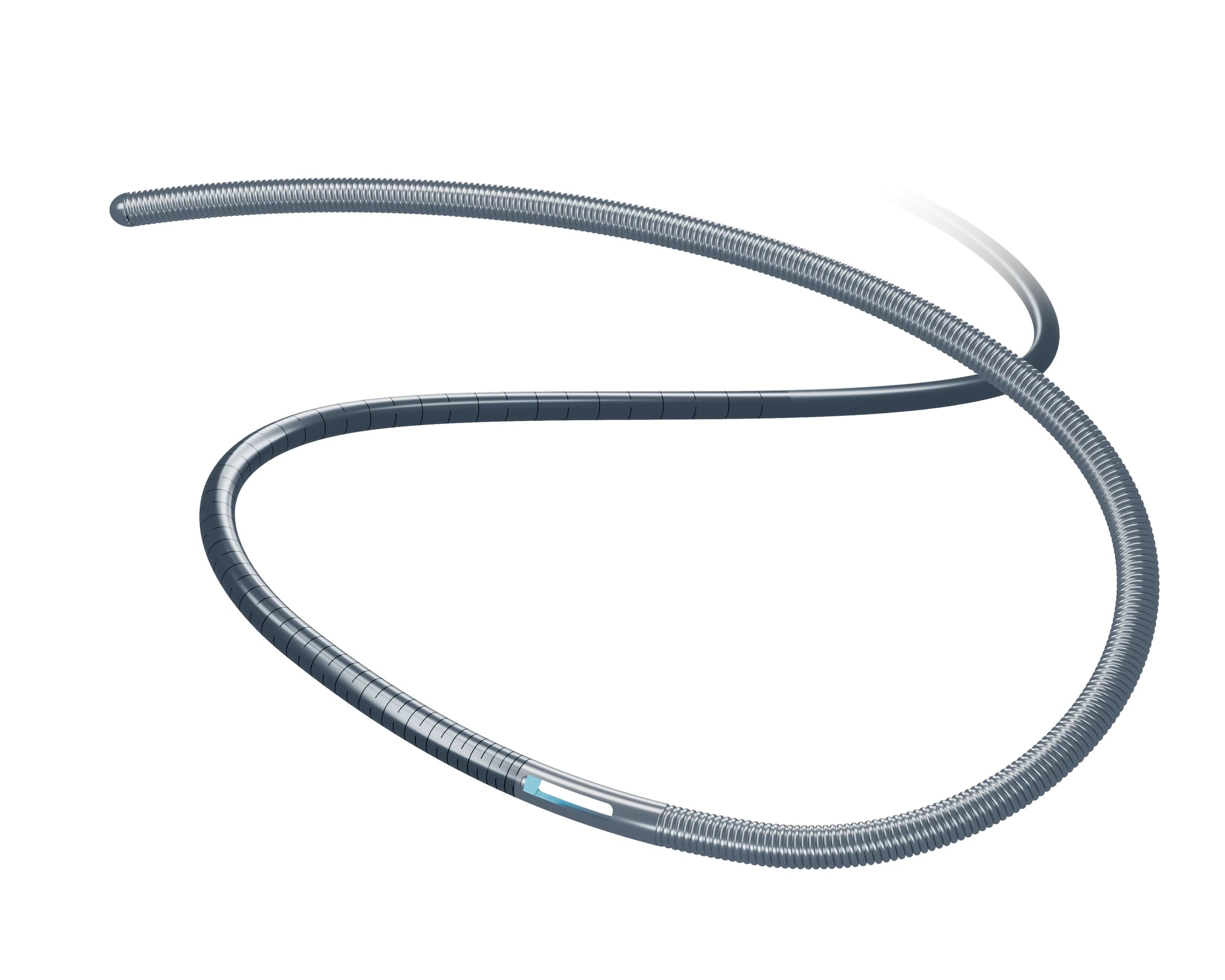
A fiber-optic pressure guidewire for coronary physiology assessment, paired with the Enlightening FFR system to display Pd / Pa and FFR results.
Current stageRegistration and clinical preparation
01 / Specifications
Key specifications & compatibility
FFR14180 dimensions, pressure-measurement performance and system requirements.
- Model
- FFR14180
- Nominal outer diameter
- 0.014 in / ≤ 0.37 mm
- Length
- 180 ± 9 cm
- Shelf life
- 3 years
- Pressure accuracy
- ±3% or ±3 mmHg, whichever is greater
- Sensitivity
- 0.1 mmHg
- Zero drift
- < 3 mmHg/H
- Distal configuration
- 35 cm hydrophilic coating; 3 cm shapeable radiopaque spring tip
Designated system
For use only with the fractional flow reserve measurement system and pressure receiver from Suzhou Enlightening MedTech Co., Ltd.
02 / Components
The product at a glance
The product consists of a pressure guidewire, torque handle and handle fiber-cable assembly. The diagram shows the wire, handle, fiber cable and pressure-receiver interface.
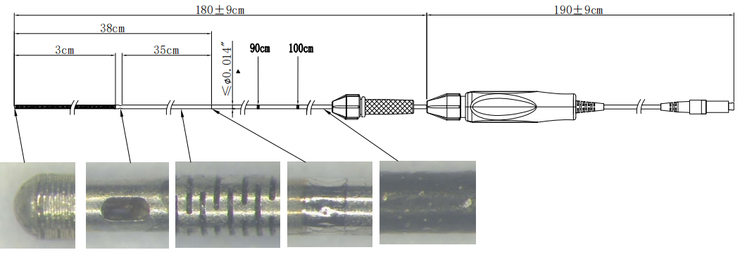
- Pressure guidewire
- Effective length: 180 ± 9 cm
- Torque handle
- Rotational control and proximal connection
- Handle fiber-cable assembly
- Fiber-optic cable: 190 ± 9 cm
03 / Distal structure
Guidewire control. Distal pressure sensing.
From distal to proximal: a spring segment, opposing sensor windows, then a laser-cut hypotube. The section beyond the sensor is a slotted tube, distinct from the wound distal spring.
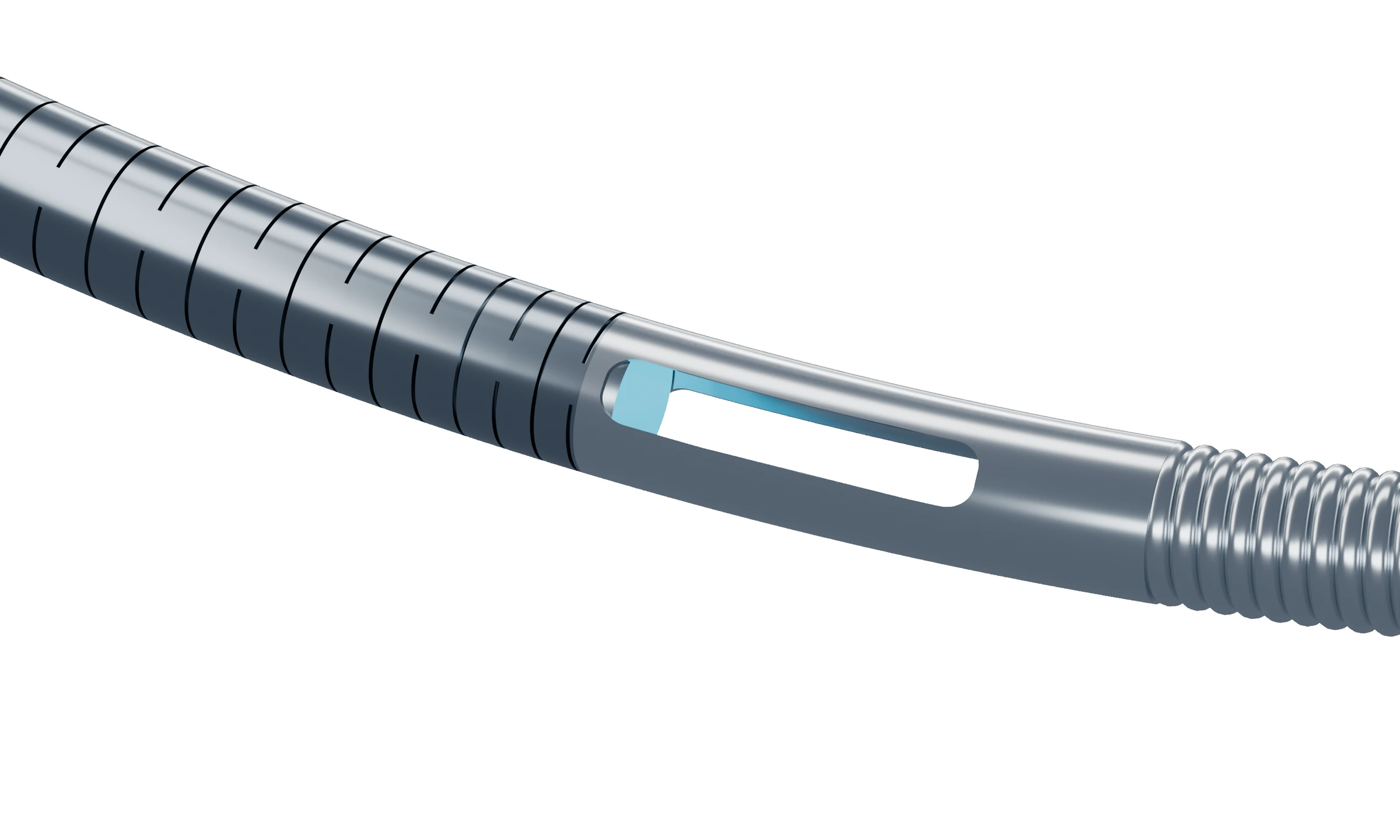
Sensing window & laser cuts
View larger imageLeft to right in this view
- Laser-cut hypotube
- Opposing sensor windows
- Spring
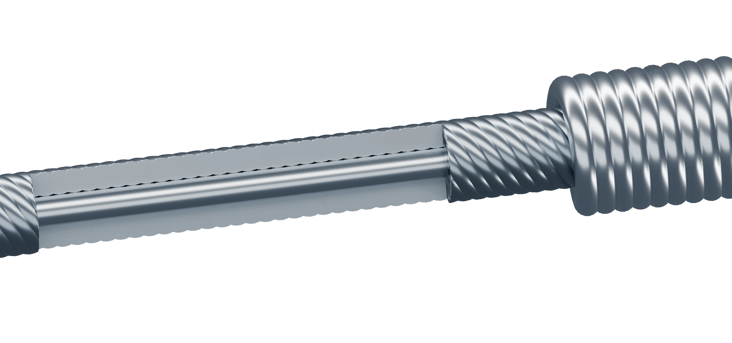
Core wire, stranded wire & spring
View larger imageFrom the inside out
- Core wire
- Stranded wire
- Spring
Rendered structural illustrations · Enlarged, not to scale; showing component relationships.
01
Distal spring segment
The radiopaque distal spring, internal core wire and stranded wire support shaping, visibility and torque transmission.
02
Opposing sensor windows
The sensor region follows the spring, with windows on opposite sides of the tube for pressure acquisition.
03
Laser-cut hypotube
A laser-cut hypotube follows the sensor region. Its surface slots are machined into the tube wall, not formed by a continuously wound spring.
04
Hydrophilic coating
A 35 cm distal hydrophilic coating supports intravascular passage and delivery.
04 / Optical sensing
Sensing principle & EMC advantages
Pressure-induced membrane movement changes the Fabry–Pérot cavity length. The system demodulates reflected light into pressure readings, while the optical signal path is less susceptible to electromagnetic interference.
How the sensor works
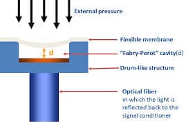
- 01
Pressure acts
Intravascular pressure causes a small deformation of the sensor membrane.
- 02
Light changes
Membrane displacement changes the FP cavity length and reflected spectrum.
- 03
The system reads
The pressure receiver and console demodulate the optical signal and display a pressure reading.
Working advantages in an EMC environment
The wire transmits pressure changes through optical fiber, without conductive signal cables, electrodes or electronic components inside the wire.
- 01FP sensor
- 02Fiber-optic cable
- 03Pressure receiver / console
- Electromagnetic interference resistance
- The optical signal path is insensitive to electromagnetic sources such as electrosurgical and fluoroscopy equipment.
- No electrical signal into the body
- The wire contains no conductive signal cables, electrodes or electronic components; no electrical energy is transmitted on the patient side.
- Defibrillation tolerance
- The fiber-optic cable has completed 360 J defibrillation-discharge tolerance verification.
05 / Before use
Key information before use
Confirm intended use, system compatibility, package integrity, shelf life, sterile single-use requirements and key restrictions.
Use & compatibility
- Intended use
- For intravascular pressure measurement in coronary and peripheral vessels.
- System compatibility
- For use only with the Enlightening FFR measurement system and pressure receiver.
- Measurement display
- The paired system displays Pa / Pd, pressure waveforms and FFR results.
Pre-use checks
- Package & shelf life
- Confirm that the package is intact and the product is within its 3-year shelf life.
- Sterile, single use
- Supplied sterile. Do not reuse, reprocess or resterilize.
- Key restrictions
- Not for neurovascular use. Protect the sensor region and fiber cable during handling.
Important
This is a sterile, single-use fiber-optic pressure guidewire. Check package integrity and expiry before use, connect the designated system and complete pressure equalization.
Product & technical enquiries
Request FFR product information
Contact Enlightening MedTech about the pressure guidewire, designated system or technical cooperation.
- Phone
- 0512 68769605